Solar Recorder
The device used for measuring daily insolation has been developed. The device was built with a PIC18F458 and the 128MB Multimedia Memory Card, MMC. The solar radiation is measured by a calculator solar cell. The PIC chip interfaces the MMC using SPI mode. The interval between samples is set to one minute. The firmware detects the memory card, assignes the file name and begins recording automatically. The LCD displays the file name, current sample and real-time ADC data. With the MMC flash technology and a cheap media card reader, the devices will be able to record huge amount of data and quick data uploading to the PC.
 |
 |
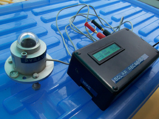
| Figure 1: The Solar Recoder with a 128MB Multimedia Memory Card. The righhand shows the input sensor made with a calculator solar cell. | |
Introduction
To estimate the sun energy for a given location, we record the irradiance (W/m^2) with time. Figure 2 shows a sample plot of irradince with time (5mins interval). The daily insolation can be computed easily by integraing the curve. For accurate total radiation measurement, we use the expensive pyranometer. However for simplicity and cheap instrument we can replace it with a small colar cell as the input sensor. The article shows the use of PIC microcontrolller and the Multimedia Memory Card for data storage.
 |
| Figure 2: Sample plot of Irradiance along the day. The insolation is 4777 WH/m^2. The Peak-Hour is 4.8. |
Hardware Schematic
The complete hardware schematic is shown in Figure 1. The MCU is PIC18F458 running at 4MHz clock. The SPI port RC2-RC5 is used to interface the MMC card. Since the memory card is +3.3V logic, we use CMOS CD4050 to translate from +5V logic to +3.3V logic. RC5 is MMC command shifted out from the MCU. The shift clock is RC3. Data out from the memory card isread back by RC4. The text LCD is interfaced to the PORTB using 4-bit mode. U2, TLV2451 is current to voltage converter. It converts the short circuit current from the solar cell to voltage signal. The output voltage is short circuit current multiplied with R5. We may adjust R5 to provide +5V full scale. The signal is tied to analog input channel 0. Channel 1 is available for thermistor input. U4 is +5V voltage regulator, the +3.3V is derived from the +5V through the use of D3 and D4.
 |
| Figure 3: Hardware schematic, click the image to open pdf schematic. |
 |
| Figure 4: The MMC socket sponsered by a company from China. |
 |
| Figure 5: The thermistor sensor tied to analog channel 1. |
 |
| Figure 6: The firmware detects MMC automatically. |
 |
| Figure 7: When the memory card has been inserted, the firmware will assign new file name (DATA_010), begin recording, display current sample (00027) and the realtime analog inputs: channel 0, 1, and 2.. |
Bill Of Materials August 6,2007 16:07:56 Page1 Item Quantity Reference Part ______________________________________________ 1 1 C1 0.1 2 2 C2,C3 30pF 3 1 C4 10uF 4 1 C5 10uF 16V 5 1 C6 1000uF 16V 6 3 C7,C8,C9 0.1uF 7 2 C10,C11 0.1uF 8 3 D1,D3,D4 1N4148 9 1 D2 Calculator Solar Cell 10 1 D5 1N4007 11 1 J1 CON10AP 12 1 J2 16x2 Text LCD 13 2 J3,J4 CON2 14 1 J5 MMC SOCKET 15 1 J6 +9V DC input 16 3 R1,R2,R5 10K 17 2 R3,R4 4.7k 18 1 U1 PIC18F458 19 1 U2 TLV2451 20 1 U3 4050 21 1 U4 LM2490 22 1 Y1 4MHz |
| Figure 7: Part List. |
Download
| Schematic | solarrecorder.pdf |
| Object code in HEX file | MMC.HEX |
New version with RTC
